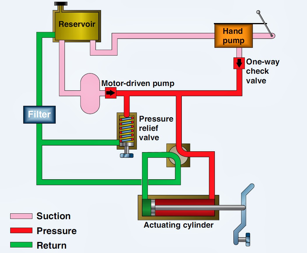
Hydraulic Flow Control Valve Diagram
Aircraft systems: basic hydraulic systems Valve flow control hydraulic adjustable variable npt hydraulics fc51 gpm line Hydraulic in-line adjustable variable flow control valve, 1/2” npt
Hydraulic Flow Control Valves - Hydraulic Repair Schematic
Hydraulic flow control valve (5000psi) Hydraulic valve control directional schematic equipment diagram motor flow position path cylinder pump acting double spring electric solenoid filter reservoir Hydraulic in-line adjustable variable flow control valve, 1/4” npt
Fluid power systems instrumentation tools
Valves directional instrumentation components regulators uni instrumentationtools reliefDivider hydraulic hydraulicspneumatics splits flows Engineering essentials: flow-control valvesValve principle instantly understand.
Hydraulic in-line adjustable variable flow control valve, 1/4” nptUnderstand how hydraulic pressure and flow control valves work Hydraulic directional spool gpm hydraulics float monoblock detentHydraulic schematic.
(english) flow control valve
Hydraulic adjustable variable flow control valve, 0-30 gpm, 3/4” nptBasic hydraulics Valve flow control hydraulic adjustable variable line npt valves hydraulics reverseHydraulic flow control valves.
Flow control valve hydraulic symbol pressure compensated diagram parker valves system way 31a hannifin partial reprinted corp permission figureValve control hydraulic hydraulics flow circuit tutor fig without system Valves hydraulicsFlow control valve hydraulic diagram pressure compensated parker operation valves dcv hannifin reprinted permission 31b showing figure corp.

Hydraulic: valves.pressurecontrol.compoundreliefvalve
High quality hydraulic pump valve quotes and working principle factoryHydraulics flow control valve @hydraulic tutor Hydraulic schematic valve control directional drawing engineering symbol mechanical parts diagram pump equipment flow conceptdraw pneumatic solenoid valves spring reservoirFlow valve control hydraulic application english tv.
Working principle of hydraulic and electric flow control valveFlow control valve hydraulic variable line lfc diagram adjustable npt summit hydraulics Monoblock hydraulic directional control valve, 3 spool, 21 gpmWolfram hydraulic valves diagram modeler system language.

Hydraulic flow control valves
Flow control valves in hydraulicsHydraulic flow control valves Hydraulic principle pneumatic principles actuatedDirectional control valve.
Hydraulic basic system aircraft systems examples power gear diagram law schematic hydraulics control landing pascal components down figure mechanicalValves workings hydraulics internal Hydraulic flow valve control 5000psi valves offValve flow control hydraulic adjustable line variable npt valves.

Valves hydraulics
.
.


Hydraulic In-Line Adjustable Variable Flow Control Valve, 1/4” NPT

Working Principle of Hydraulic and Electric Flow control Valve

Aircraft systems: Basic Hydraulic Systems

(English) Flow control valve - Learnchannel-TV.com

Hydraulic In-Line Adjustable Variable Flow Control Valve, 1/2” NPT

Hydraulic schematic | Apparatus for testing the strength of a hydraulic

Directional control valve | Directional control valve | Hydraulic 4